What is the difference between a fillet and a chamfer?
This question must have crossed your mind if you’re looking to create product designs that will be manufactured using CNC machines or 3D printers. By searching your favorite search engines like Google and Bing, you’ll likely find a ton of answers describing fillets as rounded corners and chamfers as sloped corners of a part.
But the answer to this question goes beyond just the shape of a machined part. As a product designer, you need to first understand the functional difference between these features and the design scenarios in which these features are ideal.
This article covers all of these and more.
What is the Difference between a Fillet and Chamfer?
Fillets describe rounded corners of a design (or part) that help to reduce stresses and prevent rapid deformation at the corners of the part. In contrast, chamfers are sloped or angled edges (usually at 45° or 60° ) of a design or part.
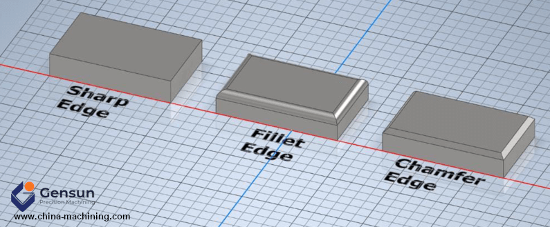
Figure 1. Fillet vs. Chamfer
Like fillets, chamfers also help to ease sharp edges, reduce stress concentration and improve the load-bearing capacity of a machined part. However, chamfers have higher stress concentration (or poorer stress resistance) since they are not able to distribute the stress over a broader surface like fillets.
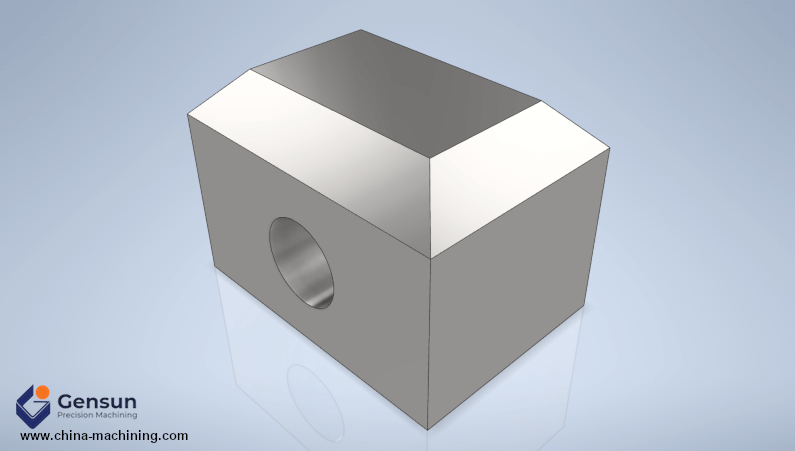
Figure 2. Chamfered edges have poorer stress resistance than fillet edges
Both fillets and chamfers improve the aesthetics of a part. However, chamfered edges are more forgiving when it comes to product designs; you can easily incorporate them in pretty much any part without having to worry about increased manufacturing costs and the parts’ functionality.
2 Things to Keep in Mind When Creating Fillet
#1 CNC Machining Bottomed Edges
Consider the illustration below where we have a cuboid part with a cavity that has an interior (or concave) fillet and an exterior (or convex) fillet.
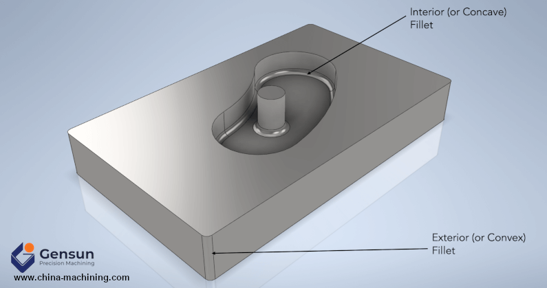
Figure 3. A machined part showing interior and exterior fillet
Bottomed edges (concave fillet) like this are especially challenging to fabricate using CNC machines as they demand specialty tools like ball end mills. Not only will this increase your manufacturing costs, but it’s also likely going to cost you more lead time since ball end mills are fragile and are used at slower cutting speeds. Therefore, you might be better off implementing square-bottom features.
But if the functionality of your design requires fillets at the bottom edges, you might want to consider using the additive 3D printing process to create your part.
Related Post: CNC Machining vs. 3D Printing: How to Choose the Best One for Your Situation
#2 Design Internal Edges Between Vertical Walls to Have Fillets
The subtractive nature of CNC milling is such that it always creates rounded corners (or fillets) between the vertical walls of a cavity, as shown in Figure 4.
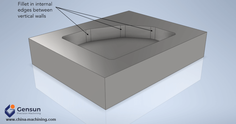
Figure 4. CNC machined part showing fillet at internal edges of vertical walls
The size of these fillets will depend on the size of the end mill tool used for the milling operation. For example, an end mill tool with a size (or diameter) of 0.8 mm can create fillets with a radius size as small as 0.4 mm. So, if you’re looking to create a cavity using this end mill tool, you can’t achieve a fillet with a radius size of, say, 0.2 mm.
Likewise, you also need to account for end mill tool size when designing fillets in regions where a vertical wall meets a curved (or angled) wall, as shown in Figure 5.
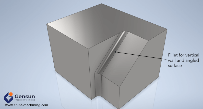
Figure 5. Fillet for vertical wall and angled surface
Keep in mind that end mill tools come in lengths of standard multiples of their diameter. We always recommend using an end mill tool with a length 3 to 5 times its diameter to get the best of your CNC machine tool.
Learn more about the different types of CNC cutting tools.
Creating Fillet and Chamfer: Gensun Precision Machining Can Help
Now that you understand the functional difference between a fillet vs. a chamfer, you can easily decide which one to include in your product design to reduce high-stress concentration and improve aesthetics. However, the success of fabricating your parts still primarily depends on your machining partner.
Gensun Precision Machining is a leading provider of CNC machining services across Asia. We have a team of highly qualified engineers and machinists capable of getting your parts done right the first time.
Learn more about our CNC machining services.

