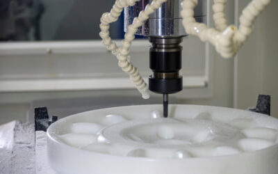
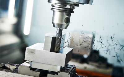
CNC machining has completely revolutionized the product development and manufacturing processes today. For instance, product designers can now create 3D CAD models and computer programs, which the CNC machine uses to automate manufacturing and fabricate parts.
However, just because CNC machining is helping to automate manufacturing, it doesn’t eliminate the need for technical drawings. For instance, technical drawings verify what you’ve got in the 3D CAD file and depict features that are challenging to convey in a 3D CAD model. Technical drawings can make your manufacturing project fast and seamless if you create them accurately.
Here, we discuss everything you need to know about technical drawings. If you’re looking to communicate your project to manufacturers efficiently and get your parts done right, this article is for you!
What are Technical Drawings?
Technical drawings are documents that contain all of the detailed 2D drawings of the part you plan to fabricate. They give a clear view of parts by depicting features (like internal and external threads, different surface finishes, annotations, dimensions, and tolerances) that might be otherwise challenging to convey using 3D CAD models.
These drawings make it easier for machinists to understand your manufacturing project, give accurate manufacturing cost estimates, and reduce the likelihood of errors during manufacturing.
Creating Technical Drawings: 5 Things to Include
Let’s assume you plan to manufacture an aluminum base piece whose 3D CAD model is shown in the Figure below.
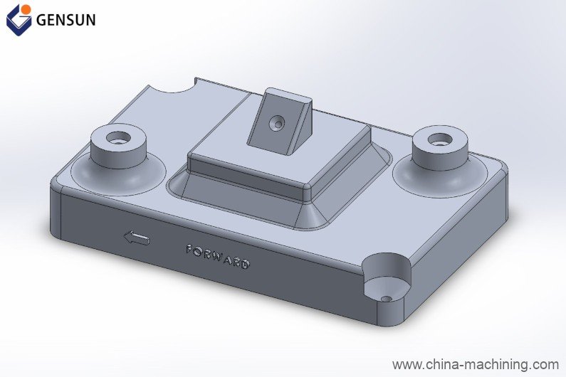
Figure 1: 3D CAD model of the proposed aluminum base piece
You might seem to have a clear picture of this base piece and its 3D CAD drawing, but this model will likely appear somewhat complex in the eyes of your machinist. For instance, this 3D model doesn’t give a clear view of all the holes, threads, dimensions, surface finishes, and other essential features. An ideal technical drawing mitigates all of these challenges, and it must contain the following parts:
1. Title Block
The title block is located at the bottom right corner of the technical drawing. It provides basic information about your product, such as the part name, part number, drawing number, your company, surface finish requirements, and the scale you chose for the drawing. Figure 2 shows the title block of our proposed aluminum base piece.
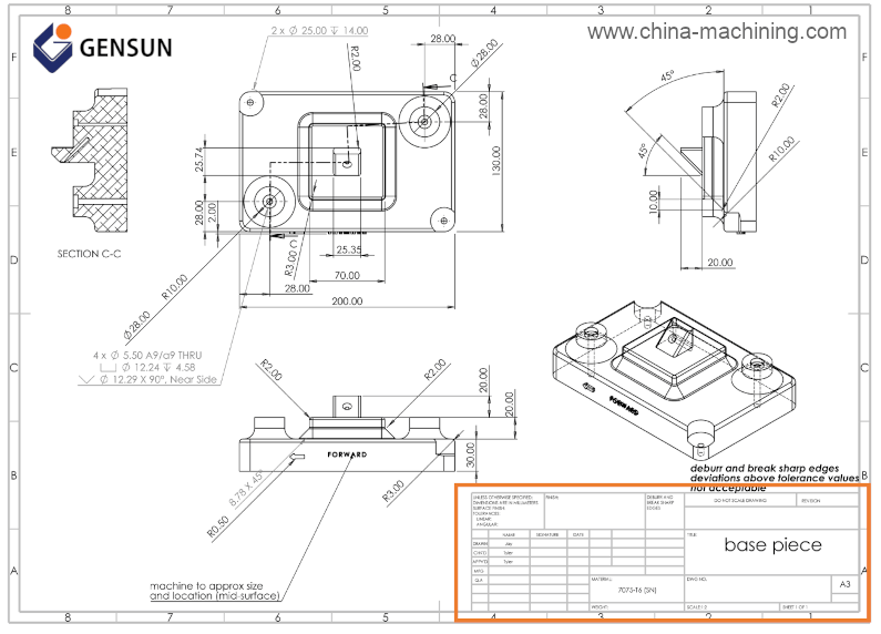
Figure 2: Title block
Other areas of the title block contain the signatures and approval dates of the different components. This information is invaluable to the machinist as it provides information about the designers who worked on the different components. It also tells them who drafted and verified the drawings for manufacturing.
2. Orthographic Views
Orthographic views are two-dimensional depictions of your part from different primary viewsㅡfront, left, right, top and back views. These views convey essential information about your part’s geometry, dimensions, and tolerances.
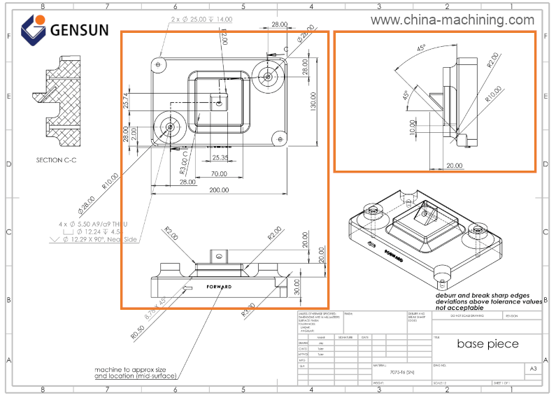
Figure 3: Orthographic view of the proposed aluminum base piece
The highlighted portion of Figure 3 shows the orthographic views of our proposed aluminum base piece, with three primary views (front, top, and end views). You’ll notice how the orthographic views depict features (like holes, chamfer, and fillets) that are not visible in the original 3D CAD model in Figure 1.
Related Post: Fillet vs. Chamfer: Understanding the Differences and Functions
3. Isometric View
The isometric view is a 3D pictorial representation of your part on a 2D surface. This view shows your part rotated 45° about the vertical axis, and 35.264° about the horizontal ㅡ which makes your part appear like it’s being viewed from above. This view makes it easier for the machinist to understand your part’s geometry and installation direction.
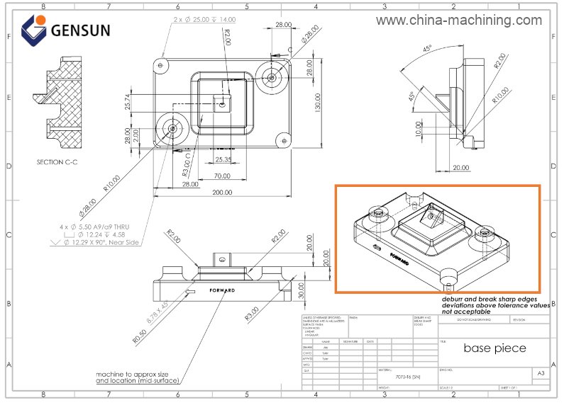
Figure 4: Isometric view
4. Section view
A section view is a 2D representation of your part when it is cut through. It lets you see hidden details (or features) that are not evident when looking from the outset.
For instance, consider our proposed aluminum base piece and assume you cut it through the plane C-C (as shown in the orthographic view of Figure 5). In such a scenario, you’d have the section view highlighted in the top left corner of Figure 5. This section view depicts the designed holes for fasteners and the wall thickness.
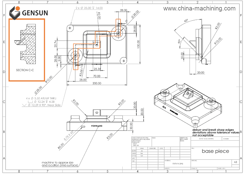
Figure 5: Section view
5. Note to Manufacturer
Notes are often included anywhere in technical drawings to communicate additional information or requirements that are not included in the drawing. For instance, you might want the machinist to break and deburr all sharp edges or utilize particular finishing methods in some of your part’s features.
Figure 6 shows two notes to manufacturers located right above the title block and toward the bottom left corner of the sheet. In this example, the note that says “machine to approx size and location (mid-surface)” simply places particular requirements on the letterings on the part’s wall.
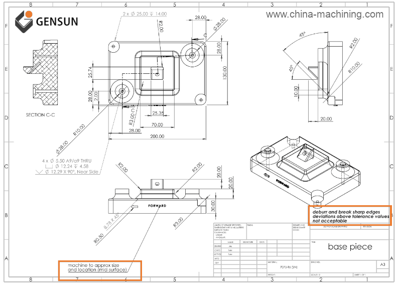
Figure 6: Notes to manufacturers
As a result, the machinist will likely consider using special CNC machining tools and implementing processes to create these letterings accurately and the finished part shown below.
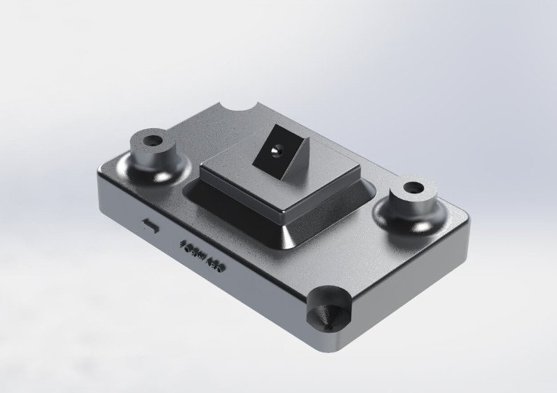
Figure 7: Machined Part Illustration
Tips for Preparing Ideal Technical Drawings for Manufacturers
The following tips will help you create ideal technical drawings that machine shops will understand at a glance.
- Choose standard templates like ASTM, ISO, and DIN templates as they are more commonly used and understood by machinists and manufacturers across the globe.
- Center your orthographic projections on the drawing sheet and leave enough space to accommodate dimensions.
- Add section views to show hidden features or complex parts.
- Use the different types of construction lines and dimensions to communicate different features. For instance, broken lines can help the machinist to identify hidden features.
- Include tolerance values in all holes, threads, and other critical parts.
- Include any note or information you think might be helpful for the manufacturer.
- Export the finished technical drawing in PDF format and send it to your manufacturer. Top-tier machine shops allow you to upload your technical drawings on their website so that they can provide you with a quote for your manufacturing project.
Gensun Precision Machining is a leading provider of CNC machining services across Asia. We have a team of highly qualified engineers and machinists capable of interpreting your technical drawings and getting your product done right the first time.
Use our quote tool to upload your technical drawings and get a quote for your project.