During the early stages of the first industrial revolution, there was no standard for fabricating machine parts. That meant every machine or manufactured product had its custom design and was built in a “one-off” production style. Although this method allowed manufacturers to achieve dimensional accuracy, it caused long lead times.
Towards the end of the first industrial revolution, Eli Whitney (the cotton gin inventor) figured out how to manufacture several muskets so that they were interchangeable ㅡ which means the muskets were identical and he could substitute them for one another. His manufacturing approach showed how components of an assembly should be manufactured to certain standard machining tolerance.
But what exactly is machining tolerance, and how does it work? This article answers all of these and more.
What is Tolerance in Machining?
Tolerance is simply a measure of acceptable variation (or deviation) in the dimension of your part. Simply put, machining tolerance allows you to specify a part’s maximum and minimum dimensional limit. It is typically expressed using “±” (pronounced plus or minus) and accompanied by an acceptable deviation (for example, ±0.05).
To better understand tolerances, consider a scenario where you’re looking to manufacture a shaft that will be coupled to a bearing, as shown in Figure 1.
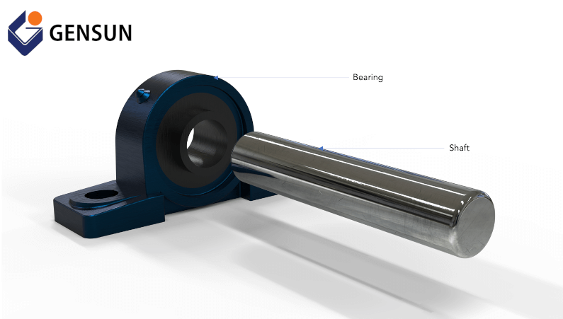
Figure 1: A shaft and bearing coupling
Suppose the bearing has a diameter of 30 mm. In such a scenario, you’d agree that a shaft manufactured to have a 30 mm diameter (or greater) might be challenging to fit into the bearing. Likewise, a shaft with a diameter of 27 mm will be too loose for the bearing.
Machining tolerances allow you to specify acceptable deviation in your part’s dimension to ease assembly. So, for instance, you can specify a shaft dimension of 29 ± 0.05 mm when manufacturing your shaft. This dimension would indicate that a shaft diameter between 28.95 mm and 29.05 mm would be satisfactory for the shaft-bearing assembly.
Types of Tolerances
#1 Unilateral Tolerance
Unilateral tolerance is a type of tolerance that allows variation from the nominal (or true) dimension only in one direction (positive or negative). An example of such tolerance is shown in Figure 2. This drawing illustrates unilateral tolerance using a shaft with a diameter of 153.65 (+2.52/-0.00) mm.
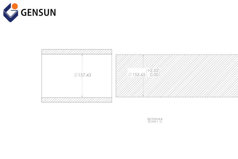
Figure 2: Unilateral tolerance
It tells manufacturers that the finished shaft diameter must be at least 153.65 mm and at most 156.17 mm ㅡ which is a sum of 153.65 mm and 2.52 mm.
Learn more: What is a Unilateral Tolerance?
#2 Bilateral Tolerances
Unlike unilateral machining tolerance, bilateral tolerances allow variation from the nominal dimension in the positive and negative directions. An example of such tolerance is shown in Figure 3, where we have a hole with a diameter of 102.00 ±0.10 mm.
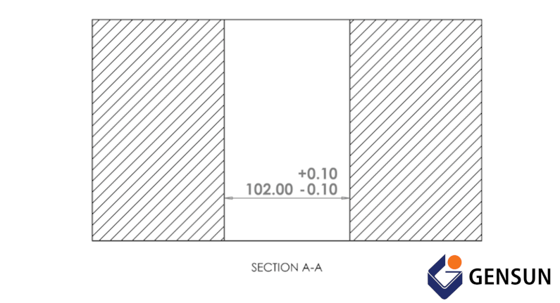
Figure 3: Bilateral tolerance
Notice how this tolerance allows equal variation from the nominal value in both directions. So, suppose your manufacturer fabricates a hole with a diameter ranging between 101.90 mm and 102.10 mm. In such a scenario, it won’t affect your part’s function.
You should opt for bilateral tolerances if you’re looking to mass-produce exterior parts since it eliminates the possibility of costly errors that would render your finished products useless.
Learn more: Unilateral vs. Bilateral Tolerance
#3 Limit Tolerance
As its name implies, limit tolerance is a type of tolerance that expresses the limit (or extreme) possible values of a part. For instance, Figure 4 illustrates the limit machining tolerance. And it tells manufacturers that the machined part (or final product) is satisfactory as long as the shaft dimension falls between 99.50 mm (lower limit) and 101.80 mm (upper limit).
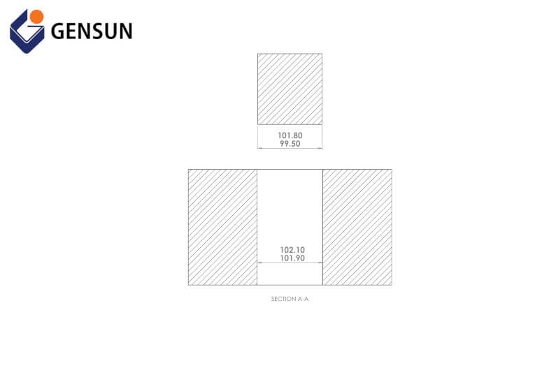
Figure 4: Limit tolerance
#4 Standard Machining Tolerances
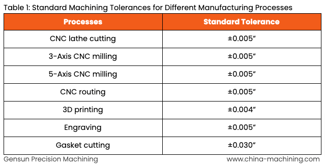
Standard tolerances are the most widely used machining tolerances for most fabricated parts today. These tolerances typically fall within the range of ±0.005” and ±0.030”, and machinists usually apply them when customers do not specify tolerance levels.
For instance, Table 1 shows the standard tolerances for different manufacturing processes:
These tolerance values are set by several international standards bodies (like ASME and ANSI). They are ideal when you’re looking to fabricate simple parts (or part features) like pipes, threads, and pins. However, for more complex part features, you might want to specify tolerances and requirements using the Geometric Dimensioning and Tolerancing (GD&T) standard.
Understanding Geometric Dimensioning and Tolerancing (GD&T)
Geometric Dimensioning and Tolerancing (GD&T) provides a higher level of quality control compared to other machining tolerances. For instance, it allows you to specify unique geometric characteristics like the true position of a feature, a part’s flatness, perpendicularity, parallelism, and concentricity.
Figure 5 shows the 2D computer-aided design (CAD) drawing of a part with GD&T. Notice how this drawing and machining tolerance provides helpful information about how certain surfaces should be parallel and perpendicular to other surfaces.
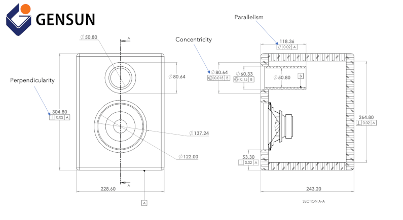
Figure 5: Geometric Dimensioning and Tolerancing
GD&T is a staple of design and manufacturing, and you’ll find top-tier product designers using this tolerancing approach with the other tolerance types for their product design. This combination of machining tolerance methods allows you to communicate your design intent precisely. It also reduces the need to explain complex requirements, especially if you’re looking to outsource manufacturing to a machine shop abroad.
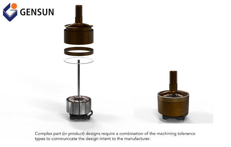
Figure 6: Exploded view and assembled view of an induction motor featuring several parts with different tolerance requirements
Manufacturing with Gensun
Machining tolerance is essential when you’re designing parts you want to manufacture. However, the success of your manufacturing project also depends on the machine shop you decide to work with.
Gensun Precision Machining is a leading provider of manufacturing services across Asia. We have a team of highly qualified machinists, engineers, and quality control experts who work together to understand your design and tolerance requirements before getting your product done right.
Learn more about our high-quality CNC machining and 3D printing (or additive manufacturing) services.

